Precision 3D Digital Twins — Drone Photogrammetry & LiDAR SLAM Technology to As-Built CAD/DWG and Revit BIM
This page walks through how Technology Surveys & Inspections turns raw drone photogrammetry imagery and terrestrial LiDAR scan data into finished 3D digital models and as-built deliverables — covering the full pipeline from aerial and ground-based photogrammetry capture, through SLAM and static LiDAR point cloud processing, to final CAD/DWG and Revit BIM output. You’ll find a breakdown of the five-step photogrammetry workflow, how ground control points (GCPs) are placed and centered for survey-grade accuracy, the architecture behind SLAM autonomy and why mobile LiDAR scans can twist out of square due to MEMS gyro drift (and the Exit GCP fix that corrects it), and how precise facade modeling comes together from combined drone and point cloud data. The page also covers how this technology serves architects, civil engineering firms, contractors, and interior design firms that need precision as-built CAD/DWG drawings for renovation, addition, and tenant improvement work — along with building owners and facility managers who rely on Revit/BIM reality capture data for space planning, asset management, and long-term facility documentation.


Photogrammetry Explained: How 2D photos are Turned into 3D Models
How do drone photos become accurate 3D models, point clouds, orthomosaics, and digital twins?
This video explains the complete drone photogrammetry workflow and shows how overlapping 2D aerial images are transformed into detailed, measurable 3D models.
Drone photogrammetry is widely used in construction, surveying, engineering, architecture, inspection, site documentation, progress monitoring, and reality capture.
More than just creating impressive visuals, photogrammetry turns ordinary drone images into actionable data that can be measured, analyzed, and used for better project decisions.
#DronePhotogrammetry #DroneMapping #Photogrammetry #3DMapping #PointCloud #DigitalTwin #DroneSurveying #RealityCapture

Precision Facade Modeling: Merging Drone & LiDAR Point Clouds
Capturing survey-grade building facades requires more than a single sensor — it demands a disciplined workflow for merging drone photogrammetry and LiDAR point clouds into one unified, accurate model.
This 8-step process covers everything from pre-merge coordinate alignment (e.g., Florida East EPSG 2226) and LAS/LAZ export, through coarse manual alignment, Iterative Closest Point (ICP) fine registration, and Cloud-to-Cloud (C2C) quality control, to noise cleaning, merging, trimming, and final export for Scan-to-BIM workflows.
Accuracy is validated using RMS error and Hausdorff distance metrics — the gold standard combination being low RMS with high Hausdorff, signaling excellent overall fit. Strategic source selection matters too: LiDAR excels at vertical facades, while drone imagery is preferred for roofs and plan views, thanks to superior nadir geometry and ground sample distance.
A proper GCP field procedure — minimum 5 control points, 10–15 second stationary captures, and careful manual target detection — ties it all together for georeferencing accuracy.
Getting this right takes real expertise. Technology Surveys & Inspections combines SHARE S-20 LiDAR and precision drone photogrammetry to deliver ≤1cm relative and ≤5cm absolute accuracy on every as-built and facade documentation project, in Florida and nationwide.

The Architecture of Autonomy: How SLAM Navigates the World
Simultaneous Localization and Mapping (SLAM) solves a core robotics challenge: to navigate, a machine needs a map, but to build a map, it must first know its location. SLAM lets autonomous systems do both at once, continuously refining position and environment understanding without relying on GPS — critical for GPS-denied environments like indoor offices & living structures, dense urban canyons, and indoor warehouses.
The pipeline moves through four stages: sensing (LiDAR, visual SLAM cameras, and IMUs capture the environment and motion), processing (feature extraction and data association identify and track landmarks), the computational core (filter-based algorithms like Extended Kalman Filters, or graph-based optimization, estimate the most likely trajectory), and refinement (loop closure and incremental map generation correct drift for a globally consistent result).
SLAM is the backbone of the same LiDAR and photogrammetry technology we deploy in the field. Technology Surveys & Inspections leverages SLAM-driven point cloud capture for accurate as-built documentation, floor plans, and facade scanning across Florida and nationwide.

Precision SLAM Workflow: The SHARE S-20 GCP & Target Standard
Accurate SLAM-based LiDAR scanning depends on rigorous ground control and field protocol — this workflow outlines the SHARE S-20 standard for survey-grade building capture, from setup through QA.
It starts with coordinate system setup (Florida State Plane zones, NAD83 US Survey Feet) and an essential field toolkit: SHARE S-20 scanner, GNSS RTK rover, Leica DISTO X6 precision laser measurement instrument, and checkerboard targets. Exterior GCP establishment calls for 4–5 control points distributed around the building perimeter, each mounted perfectly plumb at the 42-inch height standard for clean LiDAR returns.
During field capture, the continuous walk technique closes the loop at the starting point for drift correction — and scanning never begins without an RTK “Fixed” solution. Interior vertical targets serve as inter-floor tie-points, with at least one critical landing point per stairwell to stitch multi-story traverses together.
Post-processing in SHARE Point Clouds Studio reconciles SLAM drift against surveyed truth, validated through RMS and Hausdorff distance metrics.
Following protocols this exacting proceedure is what separates approximate scans from survey-grade deliverables. Technology Surveys & Inspections applies this SHARE S-20 standard on every LiDAR & photogrammetery reality capture project when providing as-built CAD/DWG and Revit BIM data.
Call us for a discussion on how we can assist on your next requirement for as-built CAD/DWG drawings.

How does a survey drone turn raw GPS data into accurate engineering elevations?
This video explains the geodetic foundation of 3D photogrammetry and why RTK drone positioning alone is not enough for survey-grade vertical accuracy. While modern RTK systems can deliver extremely precise horizontal positioning, raw GPS height is measured relative to the WGS84 ellipsoid—not true elevation above sea level.
The video also explains how GEOID18, developed by the National Geodetic Survey, converts GPS ellipsoidal heights into usable NAVD88 orthometric elevations.
Orthometric Height = Ellipsoidal Height − Geoid Height
Learn why RTK base station and NTRIP datum settings matter, and how incorrect coordinate or vertical datum configuration can introduce systematic elevation errors into drone mapping projects.
Understanding this geodetic workflow is essential for drone surveying, photogrammetry, construction mapping, topographic surveys, RTK positioning, civil engineering, stormwater design, and survey-grade 3D mapping.

Mastering Ground Control Points (GCPs): The Blueprint for Survey-Grade Drone Mapping
Ground control points (GCPs) are the foundation of accurate drone photogrammetry — well-marked, precisely surveyed spots that anchor aerial data to a real-world coordinate system. This guide breaks down the fundamentals: the Rule of Three (a minimum of three non-collinear points to lock a 3D model’s orientation) and avoiding the “bowl effect,” where too few GCPs cause flat terrain to curve like a bowl — solved with more points and oblique imagery.
Strategic placement follows the 5-Point Golden Rule — one GCP near each corner plus a center point — using high-contrast checkerboard targets (never circles, which distort into ellipses in oblique shots) and strategic elevation at high and low terrain points.
An optimized office workflow runs Aerial Triangulation first, uses a 3-photo jumpstart for predictive GCP snapping, and includes quality control checks to ensure points “hug” the terrain. In the field, RTK/PPK GNSS receivers measure each target’s exact coordinates, with independent checkpoints verifying final map accuracy.
Getting GCP placement and measurement right is what separates survey-grade maps from rough estimates. Technology Surveys & Inspections follows these exact protocols on every drone mapping project — in Florida and nationwide.

Precision in the Field: The Critical Mechanics of GCP Centering
Accurate ground control points (GCPs) are the backbone of survey-grade drone mapping, and precise centering is what keeps expensive RTK/GNSS equipment’s accuracy intact when transferring points to temporary target stands.
The 1:1 Error Rule explains why horizontal centering is non-negotiable: a pole set 1–2 inches off-point injects that same 1–2 inches of error directly into your GCP network — unlike plumb error, a centering miss doesn’t scale with height, it’s a fixed offset. Two field-proven relocation methods — the Plumb Bob Method and the Witness Mark Jig — enable precise point transfer from ground to stand base, aided by high-contrast placeholders like paint dots or nails.
On the vertical side, consistency beats absolute precision: every stand should match in height, built from one master template, within a 1/4-inch (0.02 ft) tolerance — well inside typical RTK accuracy. A final field checklist reinforces the fundamentals: double-check centering at setup and immediately before scanning, and favor hardscape over soft soil for stable, repeatable placeholders.
Precision like this doesn’t happen by accident. At Technology Surveys & Inspections, our FAA Part 107-certified pilots follow rigorous GCP protocols on every drone mapping, LiDAR scanning, and as-built project — delivering survey-grade accuracy you can build on. Get a quote for your next Florida or nationwide mapping project.

How Drones Turn Photos into 3D Models:
Drone photogrammetry converts overlapping aerial photos into precise, measurable 3D models through a five-step data pipeline, where each stage’s output becomes the input for the next.
It begins with feature extraction, where software scans every photo to identify unique, recognizable pixel groups — edges, corners, and textures visible from multiple angles. Feature matching then links those points across images, tying the entire dataset together (repetitive surfaces like brick or gravel can create false matches, which is why capture technique matters).
From there, Structure from Motion (SfM) triangulates matched features into a sparse 3D point “skeleton” and solves for camera position. Depth map estimation expands on that skeleton, calculating distance-from-camera for every point. Finally, dense reconstruction and texturing fills in the gaps using all available image data, producing a high-resolution, photorealistic 3D mesh — exportable in standard formats like .OBJ for use in CAD, BIM, or GIS software.
Accuracy at every step starts with the capture. At Technology Surveys & Inspections, our FAA-certified drone pilots use survey-grade equipment and proven flight patterns to avoid common pitfalls like feature-matching errors — delivering reliable 3D models, orthomosaics, and as-built data across Florida and nationwide. Contact us for a quote on your next mapping or inspection project.

Why SLAM Scans Twist Out of Square: MEMS Gyro Bias & the Exit GCP Fix (Mobile LiDAR Accuracy Explained)
Ever process a mobile SLAM scan of a large facility and find the interior walls bending slightly out of square — even though your start and end closure looked perfectly tight? That twist isn’t a software bug. It’s the mathematical fingerprint of MEMS gyroscope bias compounding turn by turn as you walk, and in this video we break down exactly why it happens and the field protocol that fixes it.
Using a real-world case study — a multi-wing assisted living facility scan where interior doorframes came back warped — we walk through how inertial sensors actually measure rotation, why heading error (not distance) is the real driver of SLAM drift, and the exact “Exit GCP” protocol that catches and corrects it before it ever reaches your deliverable.
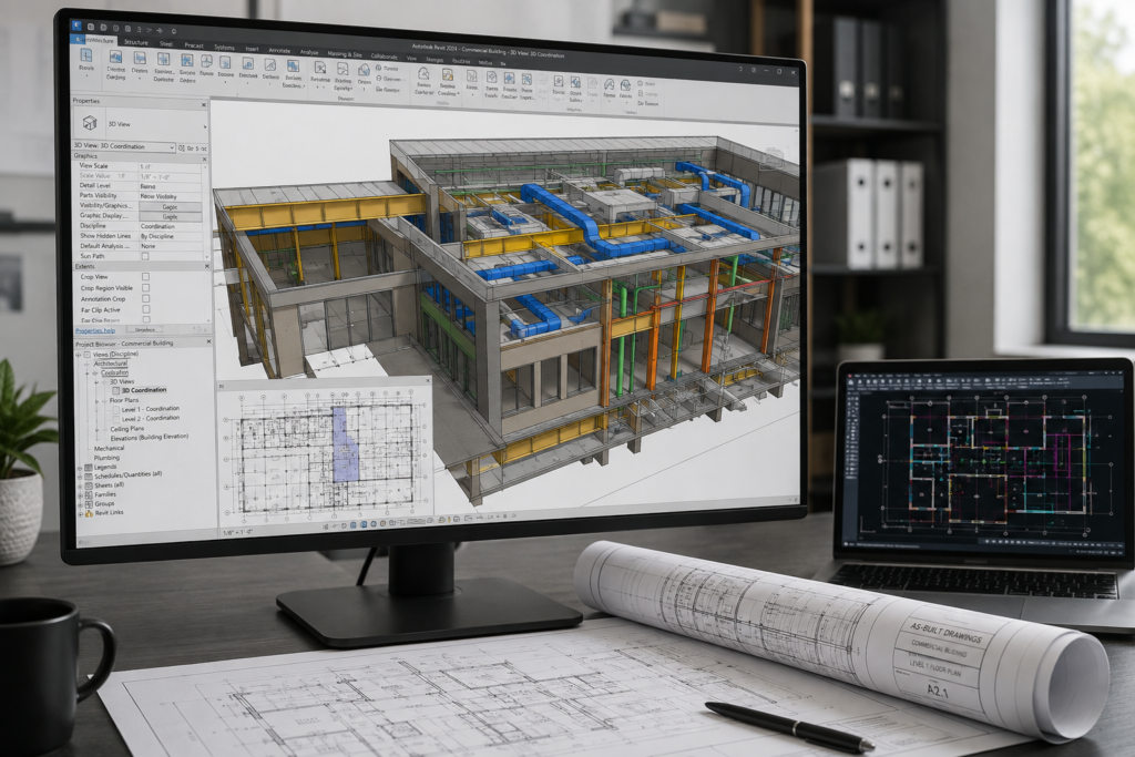
Air-Ground Data Fusion: Complete 3D Digital Twins from Drone and LiDAR Scanning for Revit BIM Models
Drone photogrammetry alone captures excellent rooftop detail but struggles with facade clarity and areas hidden under overhangs. Ground-based LiDAR solves the opposite problem — sharp vertical detail, no roof coverage. Air-ground fusion bridges this gap, merging both datasets into a single, continuous, survey-grade 3D model using Mipmap software.
The workflow depends on precise ground control: high-contrast targets surveyed with an RTK GNSS rover to establish real-world coordinate anchors and prevent model drift, while independent checkpoints verify final accuracy. A critical technique — a continuous vertical image sequence captured from ground level up to flight altitude at each control point — gives the software the visual bridge needed to mathematically align aerial and terrestrial perspectives into one coordinate space.
The result is a seamless, survey-grade accurate digital twin combining high-resolution rooftop geometry with dense, precise facade textures — the foundational dataset for scan-to-BIM conversion, as-built CAD drafting, and engineering-grade building inspections.
This level of multi-source data integration requires specialized equipment and a disciplined field protocol most inspection providers don’t offer. Technology Surveys & Inspections combines FAA-certified drone operation with survey-grade LiDAR and RTK ground control to deliver complete, accurate 3D building models — not just partial rooftop or facade coverage.
Enhance Your Milestone Inspections with Advanced Drone Technology
Florida’s Senate Bill 4-D has introduced a new era of building safety with the mandatory milestone inspections for condominium and cooperative buildings. As a leading engineering firm navigating these updated regulations, you understand the critical importance of accurate and comprehensive data to assess the structural integrity of these properties. I want to introduce a specialized service that I can provide to significantly enhance the efficiency, safety, and detail of your Phase 1 visual examinations.
As an FAA-107 licensed insured drone pilot, and certified thermographer, I specialize in survey-grade building exterior inspections, providing structural engineers and architects with the precise data needed to confidently assess a building’s envelope, roof and structural components.
My advanced drone technology offers a superior alternative to traditional inspection methods, which can be time-consuming, costly, and pose significant safety risks.
In the context of the two-phase milestone inspection process mandated by Florida Statutes Sec. 553.899 and 718.112, our drone services provide invaluable support for the initial visual examination. I can provide your team with a comprehensive and actionable dataset, including:
* High-Resolution Orthomosaic Imagery:
Detailed, scaled images of the entire building envelope, allowing for the identification of even minor cracks, spalling, and other potential defects.
* 3D Point Cloud Data:
Precise measurements and the ability to create detailed 3D models of the structure, enabling a thorough analysis of the building’s geometry and the identification of any potential deformations.
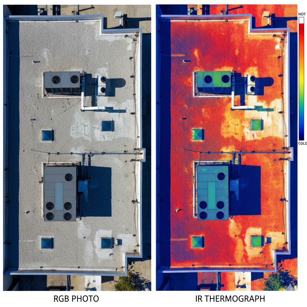
* Thermal Imaging:
The capability to detect moisture intrusion within the building envelope, a critical factor in the long-term structural health of a building, particularly in Florida’s climate.
* 4K Video Footage:
High-definition video of all elevations and hard-to-reach areas, providing a clear and comprehensive visual record for your assessment and reports.
By partnering with Technology Surveys & Inspections, you can offer your clients a more cost-effective and efficient inspection process without compromising on the quality and detail of your findings. The use of drones eliminates the need for expensive scaffolding or lifts and significantly reduces the time spent on-site. This allows your team to focus on analysis and engineering judgment, supported by a wealth of objective data.
I am confident that my specialized drone inspection services can be a valuable asset to your firm as you continue to provide exceptional service to your clients in compliance with the new Florida regulations. I would welcome the opportunity to discuss your specific needs and provide a demonstration of the data and deliverables we can provide.
Why Are Drones Ideal for Building & Construction Inspections?
Integrating drones into building inspections enhances safety, efficiency and significantly reduces costs.
Drones provide accurate data, aiding informed decision-making and addressing key challenges like workplace safety and project delays.
Here is why drones are becoming indispensable:
Efficiency and Cost-Effectiveness
Drones cut inspection times from days to hours, reducing the need for large crews and scaffolding. This efficiency lowers labor costs and allows project managers to stick to budgets while reallocating resources effectively.
Safety and Risk Minimization
Drones perform remote inspections, reducing the need for putting inspectors in hazardous areas. This cuts injury risks on construction sites, helping meet safety standards in this high-risk industry.
Structural Integrity
Drones provide high-resolution 3 dimensional imagery that can be viewed from multiple angles, allowing engineers to evaluate a building stability and prevent costly failures
Thermal Imaging Used in The Insurance Industry
The